Everyone who is expecting to pursue a career in aviation will come across aerodynamics at different levels in the field of study. In basic aerodynamics, during the study of aerodynamic forces, load factors come into play. Having a firm understanding of load factors will make things easy in the long run.
What is the Load Factor?
When boiling down the entire story on load factors into a few words, the load factor is a measure of air loads acting on an airplane. With that said, it is of utmost importance to build more ground on the study of load factors.
The mathematical representation of the load factor (n) is the ratio between the total lift and the gross weight.
n= L/W Where, L= lift generated by the wing, W= gross weight of the aircraft
As both lift and weight are kinds of forces, when calculating the load factor, units cancel out leaving the load factor dimensionless. But, as load factor is referring to a force, it is given the units of G’s. Hence, a load factor of 1 is expressed as 1G or a load factor of 6 as 6G.
Straight and Level Flight
Straight and level flight is a good flight condition to understand the load factor. When an aircraft is flying on a level flight, two forces act on the aircraft vertically: its weight acts vertically downwards while the total lift acts vertically upwards. At this moment, air loads acting on the aircraft (mainly on the aircraft wings) is equal to the aircraft weight. This is quite a normal operation of flight like cruising and the load factor is 1G. Note that airplane is not subjected to additional forces such as centrifugal force or wind gusts.
Load Factor change during a bank
When the aircraft is in a coordinated turn, flying at a constant altitude, the load factor is subjected to changes. The direction of weight remains unchanged while the total lift banks towards the turn (as the lift remains perpendicular to the wing surface). At this moment, the vertical component of the lift supports the weight of the aircraft. As the aircraft maintains constant altitude, more lift should be generated to support the weight.
In the load factor equation, gross weight remains unchanged while lift increases, resulting in a higher load factor. Let us dive a little deeper!
What will happen if the bank angle (denoted by θ) increases, will the load factor remain unchanged?
By using some trigonometry, it can be solved that,
n= 1/cosθ
At 45°, the load factor increases to 1.4G. At a 60° bank angle, the load factor further increases to a value of 2.
It is clear that the load factor changes with the bank angle, and to be more precise, it changes exponentially when the angle increases. At steep turns, there is more chance to attain maximum load factors. The below image shows the relationship between these two parameters.
With the change of load factor with the bank angle, aircraft stall speed increases. Stalling speed is where the aircraft wings no longer generate lift due to flow separation of turbulent air. The following equation shows that accelerated stalling speed (altered stalling speed due to load factor change) is proportional to the square root of the load factor.
As an example, consider an aircraft flying with a stalling speed of 100 knots with a load factor of 4. Under these new conditions, a premature stall occurs at 200 knots. So the pilot should be responsible for avoiding steep turns at slow speeds.
Performing steep turns when the airplane is moving through turbulent air may jeopardize safety as the airplane is passing through a region of the highest load factors.
Can passengers feel a Load Factor change?
Yes, passengers can feel both negative and positive load factors. As an example, assume an airplane flying straight and the pilot moves stick forward diving the airplane. Passengers will feel slight weightlessness during the maneuver. The pilot moving the stick backward disturbs the level of flight and the airplane climbs creating a positive load factor and occupants will feel heavy.
In a turn, occupants are supposed to feel the G loads, but large commercial airliners such as A320 or B777 are not performing steep turns at a high maneuvering speed that makes the effects of load factors insensible. In very rare occasions such as a 60° bank, the load factor increases nearly by 100% and the force applied is too high, occupants may feel heavy due to higher total lift and the centrifugal force.
It should be noted that not only pilot intended maneuvers such as banking the airplane, putting the airplane into a dive or a climb alters the load factor. Aerodynamic forces such as wind gusts that will deflect the airplane from a straight line produce stress on the airplane structure. This alters the lift-to-weight ratio or the load factor.
Why the Load Factors are important
It is proven that the load factor increases on a bank, in other words, higher air loads act on the aircraft structure. So the aircraft designers have used load factor as a safety parameter to define the aircraft operating envelop.
For each aircraft design, there is a maximum load factor that can attain without any structural damage. These load factors are referred to as limit load factors. At this moment, the aircraft structure is experiencing the maximum allowable structural load. Any aircraft surpassing limit load factors during a maneuver breaches its safety envelop.
Airplanes are listed under various categories based on the limit load factor to cater to various operational situations. These load factors are normally found in Pilot’s Operating Handbook (POH) or placarded on the cockpit.
Transport Category -1.0 to +2.5 Gs
Normal Category -1.52 to +3.8 Gs
Utility Category -1.76 to +4.4 Gs
Acrobatic Category -3.0 to +6.0 Gs
It is clearly seen that the acrobatic category inherits a higher limit load factor greater than other categories as these aircraft are performing high G maneuvers and the designers have strengthened the aircraft structure to withstand relatively high load factors. An airplane serving under the utility category has relatively higher load factors to support more cargo, hence the structure is designed to withstand higher than normal forces.
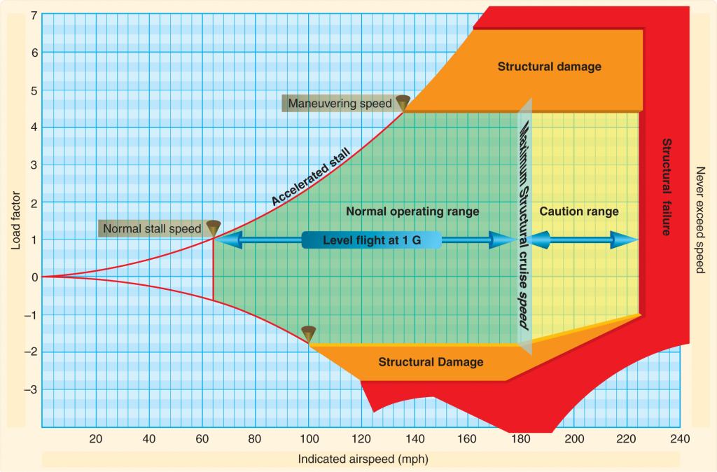
Vg Diagram
A Vg diagram plots the load factor against the indicated airspeed. For each airplane, a peculiar Vg diagram is available at a certain weight and altitude. More critical data can be extracted from a Vg diagram.
Two curved lines creating a cone shape depict the maximum lift capability of the airplane. At the normal stalling speed or the wing level stalling speed, the airplane is only capable of producing a load factor of 1G. As mentioned earlier, the square root of the limit load factor is proportional to the stall speed (Vsacc = Vs × √G.). This results in the exponential behavior of the maximum lift capability line.
The green region indicates the positive and negative load factors an airplane can attain during the normal operation. The intersection of the positive limit load factor with the line of positive maximum lift capability is the point where the positive limit load factor is achieved aerodynamically. This point is referred to as the maneuvering speed and an airplane operating above this speed can generate forces large enough to cause structural damage. On the other hand, the intersection of the negative limit load factor with the line of negative maximum lift capability is the point where the negative limit load factor is achieved aerodynamically and airspeeds above this point create a negative load factor that would damage the airplane. Maneuvering speed is normally mentioned in the Aircraft Flight Manual (AFM) and is placarded in the cockpit for the pilot’s attention. There is no cockpit instrument indicating this speed.
Image source: A Typical Vg Diagram. Link: http://learntoflyblog.com/wp-content/uploads/2016/01/4-47-1024×674.png
The pilot should not attempt to exceed the never exceed speed or the red line speed as it can lead to structural damage or instant structural failure leading to a catastrophic accident. As per the graph, an airplane can be pushed into the region of structural failure even in level flight without attaining higher load factors but gaining an extremely high speed.
Want to read more like this?
Enter your email and get curated content straight to your inbox!
Thank your for your subscription.
You are already subscribed to this newsletter.
Aeroclass Team
A team of professionals with a deep passion for the aviation industry bringing you the newest and the most striking industry-related news and content.
Leave a comment
Recent posts
“Remove Before Flight” Tags on Aircraft
Aircraft · 6 min read
The superficial meaning of the words "Remove Before Flight" is "remove these tags before the plane takes to the air". What it really means is to remove all the protective covers and pins that protect against third-party objects before a flight.
Jun 19, 2024
How Fast do Planes Fly
Aircraft · 4 min read
Travel by plane became the main option for reaching the places people never dreamed of seeing long decades ago. Not just because we are talking about one of the main means of transportation capable of reaching places previously inaccessible - or challenging to reach - to most people.
May 31, 2024
Surging Aircraft Leasing Market Fuels High Demand for Expert Talents
Aircraft · 1 min read
The global aircraft leasing market, which has been on a steady rise for a number of years, is expected to surge to even greater heights in the coming decade. By 2029 the aircraft leasing market is estimated to reach the value of almost 300 billion USD.